It is Dec 30 morning and I went up the roof to see the progress and I saw 5 panels mounted exactly to my specifications:
 |
| 5 solar panels mounted on an elevated iron rail. |
After a while, we've started laying down the wiring from the solar panel. To connect from the solar panels, you need to use a standard connector called an MC4.
 |
| MC4 connectors |
 |
| AWG#14 wire with MC4 on one end and laid to ground |
 |
| wires connected to the solar panel |
Dec 31, it is new year's eve but we still worked on the project. I still do not have yet the needed equipment for the power room like the disconnect switches, etc. I ended up ordering them online as finding them locally will take some time and I have to wait out the entire holidays, and I can't wait for it. I also ordered online the much needed DC current clamp meter. Both will be shipped via express shipping. So while the equipment arrives, we rigged a temporary connection. Luckily, everything is available except for an AC outlet and its cover so I went out on a holiday and fortunately, there is an open family hardware store which sells them and I bought it.
 |
| GTI finally connected (temporarily) to the solar panels |
 |
| Roof mounting is complete |
That night, fireworks have began. I went back to the roof near the solar panels near 12 midnight and shot this video:
Happy New Year!!
January 1, new year's day and it's the first day the grid tied solar array system went online for a whole day and I monitored the power output using the watt meter:
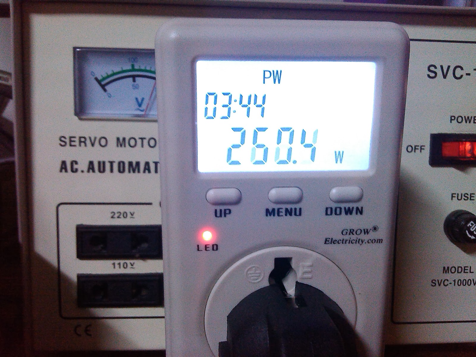 |
| Watt meter measuring 260W output power during mid day. |
6:45am 17w
7:00am 46w
8:00am 156w
9:00am 211w
10:00am 242w
10:30am 260w
11:13am 267w
11:30am 280w
12:40pm 262w
1:00pm 236w
Total energy produced for Jan 1 was 1.454kwh
Jan 2, today, I used my other watt meter instead, the Voltcraft brand. By noon, during it's peak output power. I noticed the watt meter is displaying 0 output and the GTI is not recycling, usually it recycles in 1-2 secs after it detected a change in solar output. I turned off the GTI and back on and then it recycled. Seeing that is was unusual, I simulated a power outage by turning off the AVR (automatic voltage regulator) where the GTI output and watt meter is connected and turning is back on. I got startled when I heard a weak 'pop' in the watt meter and the display did not turn on. Guess what, the watt meter is busted! My guess this Voltcraft meter does not like power surges, it was damaged one time during its warranty period and I got it back repaired. I will try to have it repaired again this time out of warranty. Fortunately, nothing else is damaged so I installed back the cheap watt meter and put the GTI back online.
Due to that incident, I have no output data for today.
I will make another update once new equipment have arrived or there is new progress.
Ei, project is looking good! hope the other watt meter will get repaired soon...
ReplyDeleteThanks for giving us an update on your solar panel project. BTW, nice fireworx vids!
Last time it broke, it took about 4 weeks before I got it back.
DeleteThanks!
Not sure my first post went through. If so, feel free to delete this one.
ReplyDeleteI was asking, what is the distance from your panels, especially the farthest one, down to where they connect in your power room on the bus bars? I would think that #14 gauge would be a little small for the panels. Isn't the typical wire size coming off a panel, #10 gauge? Perhaps some of your loss is due to this?
Hi,
DeleteThanks for commenting. I did mention that the AWG#14 wire can be used up to 5.9Amps. My reference is this: http://diyaudioprojects.com/Technical/American-Wire-Gauge/
The 100W pv panels I have can only produce less than 6A each when short circuited. I thought before that the wires are too thin but later realized than the size is just right. After the bus bar I did changed the wires going to the new GTI (see my later blogs) and I used royal cord which is about AWG#9 when all 3 wires were combined. Back to your original question, the max distance from my farthest PV to the bus bar is about 5m.
Fair enough. But, when viewing that table, I didn't see what distant 5.9 amperes would be good for. I seriously doubt it would be for 10 meters, which is what you should be calculating, round trip, not one way.
ReplyDeleteI use this particular scale.
https://www.dropbox.com/s/qvwo9kvrbip9bfi/DC_wire_selection_chartr.jpg
If your distance is 5 meters, again, that doubled would be 10 meters for a round trip run. This, roughly, would be about 30 feet. I would suggest increasing the size at least to #12, preferably #10, for that length. I believe you would see an increase in power harvested.
Thanks for sharing the scale. Initially I did plan on using AWG#12 for the PV cables but as stated, the AWG#14 is what is in stock and no cost for me. Replacing the cables will add cost and for a 600W PV system, I estimate the gain will only be <50W. Changing my GTI to a 24V system did increased my output by >100W for the same cable. I'll definitely use your guide on my next phase. Thanks
DeleteIs this system in the Philippines? If so, where, if I may ask? City or Province? I am American, but lived in the Philippines for more than 11 years. I still maintain an apartment there, and hope to return later this year, actually.
ReplyDeleteYes it is in the Philippines, particularly in Bulacan province.
Delete